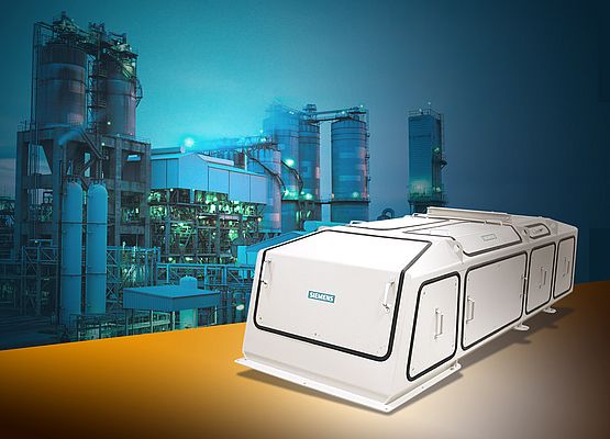
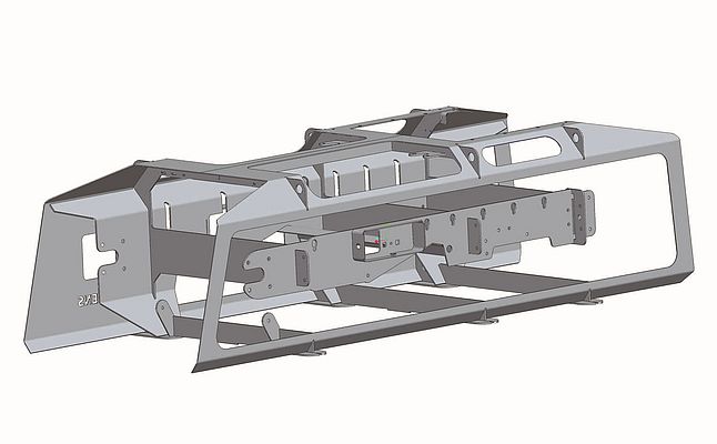
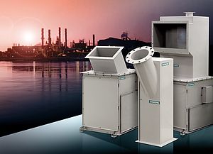
To maintain competitiveness in the handling of bulk materials, innovative design aligned with the power of 3-dimensional engineering software were used to redesign medium and heavy-duty weighfeeders. The overall project goal for the redesign of the medium- and heavy-duty weighfeeders was to optimize the entire design while maintaining competitiveness. Optimizing the design entailed reducing the time required to replace the seamless conveyor belts, improving access for general maintenance and inspection, developing an automatic belt tracking and tension monitoring device and increasing the rate capacity. To maintain competitiveness in the weighing market, it was necessary to develop a design suitable for global manufacturing while adding configuration options. This meant creating engineering software tools to manage the infinite number of configurations and provide the models, drawings, and instructions required to design and build each customer order. Business model and design philosophy Prior to the redesign project, weighfeeder designs could only accommodate a fixed number of configurations. Parts and sub-assemblies were stocked in a warehouse which allowed for relatively quick order turnaround provided the order fit into the existing weighfeeder size domain. This process was difficult to manage and costly to keep the required variety of parts in stock. Order fulfillment was further complicated by the large variety of custom parts required to accommodate various measurement methods worldwide. For example, some areas of the world use metric belts, shafts, and other components while other areas use imperial measurements. To achieve the goal of increased rate capacity, it was necessary to expand belt width options and pulley diameter options as well as the specification for the height of material on the belt. For all these reasons, it was unrealistic and costly to keep adequate stock on hand for the existing weighfeeder design. Although each assembly relied on a general model of a standard feeder, many design aspects required customization. It was not feasible to re-model an entire set of parts and create a specific assembly model for each order. Also, the configuration centers needed more support from the design team in this regard. To increase market advantage and to deal with the configuration, customization and order management issues, a new modeling philosophy known as the “Top-down design approach” was adopted. The top-down design approach starts with a 'skeleton' which is the shell for the product. All other design elements flow from the top-down as opposed to designing each incremental piece and trying to fit them together like a jigsaw puzzle. This approach is part of 3D engineering software. Various experts were consulted to assist in the customization and development of the new system. This was the initial step in the creation of a robust parametric design system that would allow the weighfeeder geometry to be easily resized. That is, weighfeeder designs would be based on a 'skeleton'-type frame. The software would automatically adjust the weighfeeder 'skeleton' to accommodate various sizes; growing and filling in idlers, panels or other design features as needed. When finalized, the software would provide a complete package suitable for manufacturing each weighfeeder production order. This meant standard parts could be stocked in low quantities, but most of the parts would be purchased just in time for each order, providing lean manufacturing. Conventional design Initially, a complete review of the weighfeeder design process was performed and opinions from other designers, customers and service personnel were gathered from all over world. The previous weighfeeder designs were cantilevered to support the middle area and the components between the belt strands to allow removal of an endless belt. Due to that design, the weighfeeders required almost complete disassembly of the top half of the weighfeeder to remove the skirt boards, cover panels and support posts. This required a significant amount of downtime for belt replacement, lowering overall plant productivity. Previously weighfeeders were made of a steel frame constructed from sheet metal parts and standard-sized steel sections (i.e. c-channel, square, round, or rectangular hollow sections). This construction method involved creating small welded assemblies which are bolted together to create a rigid frame. A significant amount of time was required to fabricate these small welded areas and bolt them together for final assembly. Guarding is required for all enclosed weighfeeders to cover pinch point hazards and help contain dust. Prior to the redesign, individual sheet metal panels were fastened onto the support frame using bent flanges, tapped holes, or blind nuts with bolts. The panels had to fit around structural frame members, which made them difficult to install and remove. Therefore it was time consuming to gain access for inspections and maintenance, in some cases so time consuming that some customers simply left the covers off the weighfeeder, creating unsafe conditions. An additional concern with the cover panels was that while they do provide adequate pinch point protection, they did not add much rigidity to the strength of the machine during installation, operation or during belt change. This was an inefficient use of raw materials – extra material used in the design did not lead to an increase in structural support. The weighfeeder designs up to now used standard steel sections in common metric or imperial sizes. The availability of these sections was dependent on the regional area of production making it difficult to create a globally configurable product. Some regions have components readily available while others did not. The previous design process did not readily allow for the application of theoretical loads to test the design. It was therefore challenging for the design team to configure a 3D model of all the possible combinations and perform structural analyses efficiently. 3D design innovation The new design is drastically different from the old, made possible by the 3D engineering design software. The first step in the weighfeeder redesign was to place all the components that make up a weighfeeder into the new parametric assembly model (i.e. the belt, idlers, pulleys, and load cells). After several design iterations, a set of parts was developed to support the weighfeeder components while maintaining the cantilevered frame. This new patent-pending design is known as the “unibody”. It consists of at least three cross-frames, two side rails and an outer shell all made from plate steel in varying thicknesses. “E” shaped cross-frames, spanning the width of the belt (located behind and in front of the inlet and at the discharge) provide increased structural support. Running perpendicularly to the "E" frames are the side rails which hold the idlers and shaft bearings. One side rail, substantially more rigid than the other, is on the non-access weighfeeder side for belt changing. The other, on the access side, is attached to the cantilevered center arm of the “E” frames and is sized to conveniently allow the seamless belt to pass over it during a belt change. To tie the rails and "E" frames together, thinner gauge plate steel is cut, formed and welded to the outside creating a rigid one piece shell, hence the unibody design name. The plate steel parts used in the new design are cut so that they fit together closely and are stitch-welded along their joints to provide increased strength. The overall time to perform the welding and the bolting of loose parts is far less than that required in the previous design and helps to keep costs down. The design of an enclosed weighfeeder with fully-guarded pinch points now incorporates access panels and guards into the unibody shell. The panels and guards are integrated into the openings of the outer steel plate and are connected with simple latches. It is the most efficient use of raw materials possible and it gives the customer easy access to key areas of the weighfeeder. The new design contains only plate steel parts and can be configured in any manufacturing region around the world. The choice of using metric or imperial plate thicknesses is available without jeopardizing the general design arrangement. Also, the new software easily allows configuration of 3D parametric models. Further, the design team can now perform structural analyses through the software models for the sizes required. This will allow the engineering team to design effectively and enable the most efficient use of raw materials. Rate capacity Frequently the design team received requests for weighfeeders to meet applications outside of the rated design range. Custom designs were often created that required significant engineering effort, time, and resources. With the new weighfeeder design and unibody structure in place, it is now possible to increase the rate capacity of the weighfeeders. The SITRANS WW300 weighfeeder meets weighing market demand for products that can handle weighing applications up to 800 t/h. As a result of the increased design rate, the device features wider belts, larger pulleys, and increased material depth. Thanks to the 3D software, the new unibody design can easily accommodate the larger sizes of belts, pulleys, and material depths by simply increasing the width, height, and thickness of the "E" frames to suit each application without disturbing the arrangement of the parts. Computer generated models are sized to match the actual weighfeeder allowing virtual structural analyses to be performed. This ensures that the required strength is achieved in the final product. The software creates manufacturing drawings automatically simplifying the engineering required to produce a weighfeeder. New configuration options and special devices One of the project goals was to increase configuration options and to develop an automatic belt tracking device. With the previous design, several of these configuration options were customized. Going forward, they are incorporated into the main assembly model as options that can be simply turned on and off depending on customer requirements. The weighfeeder options include: automatic belt tracking and tension monitoring device, sealed enclosure, impact idlers, dust curtains and inspection ports. The advantage of adding these configuration options into the parametric computer model is that the model automatically adjusts the overall geometry of the weighfeeder, along with the individual components. Conclusion The combination of powerful 3D engineering software and design innovation gives Siemens Weighing Technology a significant competitive edge. Not only is the weighfeeder product line meeting a broader range of capacities for the weighing industry, but the software gives the designers advanced tools to engineer a complex yet customized product line efficiently, economically and structurally sound. With the unibody design, the weighing technology team met all of the goals established at the beginning of the project. The ability to manufacture globally in a timely manner will undoubtedly create more market opportunity for Siemens weighfeeders. Through the software, complete 3D models will be created for each weighfeeder order. This means the customer will be able to see an accurately scaled assembly drawing of the product before it is purchased. This creates additional confidence when integrating the weighfeeders into applications. The custom engineering of Siemens weighfeeders ensures the perfect fit, no matter what the application.
3D software for weighing design
engineering software used to redesign medium and heavy-duty weighfeeders
- by Siemens AG
- February 11, 2011
- 10272 views


