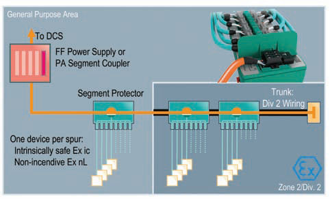
Ignition protection type Ex ic is intrinsic safety. It is very similar and replaces protection type nonincendive Ex nL which becomes obsolete in 2011. How to switch easily from non-incendive to intrinsically safe fieldbus design? The energy limiting ignition protection type Ex nL (non-incendive) has been available to fieldbus users for years paving the way for instrumentation in the increasing number of hazardous areas, Zone 2. The different name compared to the intrinsically safe protection type Ex ia and contradictory requirements have lead to ambiguity regarding correct dimension and construction of electrical circuits rather than the expected savings in installation and maintenance cost. Ignition protection type Ex ic (IEC 60079- 11:2007) is intrinsic safety. It is very similar and replaces protection type non-incendive Ex nL (IEC 60079-15) which becomes obsolete in 2011. With Ex ic installation is required to follow demands of intrinsic safety: separation of intrinsically safe and other circuits with a tight string length min. of 50mm. Ex ic circuits require either marking or a light blue cable. Validation for Ex ic fieldbus circuits follows the two popular methods Entity and FISCO. Fundamentally, the way how fieldbus segments are designed remains the same. The industry standard of Trunk-and-Spur topologies remains the same. Existing topologies continue to be valid. Most specifications today demand short circuit protection for each spur in order to protect the trunk and remainder of the segment from unwanted faults typically caused by live work on devices. Thus fieldbus couplers with short-circuit protection, called Segment Protectors (SP), are typically used. Significantly higher availability of the fieldbus infrastructure is the result. The fieldbus power supply already contains voltage control and the Segment Protectors contain current limitation. So the simple and reliable way to put Ex ic ignition protection into practice is to beef up those two circuits in their electric design to comply with demands from the IEC standard. In combination the power supply and the Segment Protector realize intrinsic safety Ex ic at the spur. This design is known as the High-Power Trunk concept already an industry standard for any hazardous area. Since the trunk’s power is unlimited with regards to ignition protection, live work at the trunk is permitted only with gas clearance. However, hot work on instruments is permitted anytime. Not only cost-effective this design makes best use of the segment by allowing a higher load current on the trunk. More devices can be connected in comparison to energy limitation at the power supply. This lead to a re-engineering of the FieldConnex system components for fieldbus infrastructure. Only minor updates were necessary to qualify isolation levels of the FieldConnex Power Hub and R2 Segment Protector for Foundation fieldbus H1. The most obvious change is a plastic separator wall introduced to the R2 Segment Protector to incorporate the 50 mm tight string length between the intrinsically safe and non-intrinsically safe circuits. Similarly the Power Hub receives covers for its bulk power supply connections to clearly separate them from both, the host and spur connections. Validation now follows the already known concepts for intrinsic safety according to Entity or FISCO. Those fieldbus planners that already separate non-incendive (Ex nL) from power circuits are well prepared. Ex ic brings intrinsic safety to Zone 2. With its requirements adapted to the risk of explosion protection it reduces cost and removes ambiguity. Working with in fieldbus instrumentation should be as easy as always. With Ex ic it is.
Fieldbus in Zone 2 - Intrinsic Safety Ex ic
Ignition protection type Ex ic is intrinsic safety. It is very similar and replaces protection type nonincendive Ex nL which becomes obsolete in 2011.
- by Pepperl + Fuchs SE
- November 1, 2009
- 1130 views


