During the commissioning of an Air Separation Unit, several failures have occurred with similar damages, in one of the pinions of the multiservice Integrally Geared Centrifugal Compressor covering both Main Air Compressor and Booster Air Compressor, exactly the BAC first pinion.
The cooperation between the compressor supplier, the manufacturer of the system, a rotating machinery consultant and a metallurgical laboratory has allowed to successfully solve the problem, reaching the correct operation of the unit.
Rotordynamic Analysis
Comparing the results of the calculation of the vibration with bearings in the final set-up with the measurements carried out on the rotor during a shut-down (Fig. 4), an acceptable agreement for the critical frequencies, despite the approximation of gear effect calculation, was found.
Torsional Analysis
It was also carried out a torsional analysis of the compressor train, considering the lumped parameters model shown in Fig.5.
The torsional stiffness of the gear teeth was calculated in accordance with API 684 2nd ed. Para 4.2.2. The first six Undamped Torsional Natural frequencies are indicated in the following table. The system exciting torque frequencies are the rotation speed and the power supply frequency.
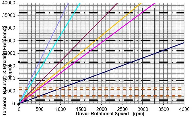
Campbell diagram (fig.6) shows that only two exciting torque frequencies cross natural frequencies within the operating range:
• the 1st exciting frequency coming from the MAC pinion crosses the 3rd natural frequency,
• the 2nd exciting frequency coming from the MAC pinion crosses the 6th natural frequency.
Following figure shows the torsional mode shapes of the system.
As it can be seen the shaft affected by the mode shapes are the following:
• 1st and 3rd mode shape: only driver shaft
• 2nd and 4th mode shape: mainly MAC pinion and, to a lesser extent, driver shaft
• 5th mode shape: only driver shaft
• 6th mode shape: mainly 1st BAC pinion.
Since the 3rd and 6th mode shape do not affect the MAC pinion, the above mentioned crosses has not to be considered as a critical conditions and the system has to be considered acceptable.
Conclusions
The rotordynamic analysis of the rotor made it possible to finalize the Root Cause Analysis of accidents, confirming the primary cause previously defined and supported by the morphology of the damage to the bearing detected by the metallurgical laboratory.
The little clearance of the rotor bearings, accentuated in the starting transient, caused the high temperature and pressure of the oil film, resulting in deterioration of the white metal of some pads. During the shut-down due to the high temperature of the antifriction metal of the bearing pads, the rotor crossed the lateral natural frequencies with very high vibration amplitudes, because of the deteriorated bearings, thereby causing the impeller rubbing against the stator.
The implemented multidisciplinary analysis and team work have enabled an effective identification of the causes of the event, reducing time and costs for the solution of the problem and giving the customer the necessary confidence about the basic robustness of the compressor design.


